


How does underwater photogrammetry work?
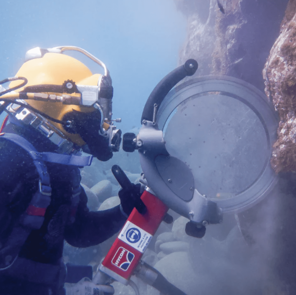
Turning scattered digital photographs into reliable engineering models underwater seems counterintuitive given how water bends light, dims color, and scatters clarity. Yet the underlying math remains rock-solid when executed properly.
Understanding the transition from raw image acquisition to a calibrated three-dimensional mesh helps asset owners evaluate survey proposals. Deploying underwater photogrammetry requires a methodical, multi-stage workflow combining field discipline with rigorous computing power.
The physics and science behind underwater photogrammetry
Capturing visual data through water requires accounting for severe refraction. As light transitions from water through a glass port into an air-filled sensor chamber, its velocity and angle change dramatically.
This index of refraction bends incoming light rays, alters focal lengths, and causes barrel distortion. Without precise geometric calibration, reconstructed digital models warp, curve, and fail engineering tolerance standards.
Correcting optical refraction during underwater photogrammetry
Survey teams neutralize refraction using precision-engineered hemispherical dome ports or specialized corrective lens assemblies. Dome ports preserve the natural field of view and prevent chromatic color fringing along the image periphery.
Before surveying, operators calibrate camera sensors inside water tanks using known dimensional targets. The software logs optical aberrations, radial distortion parameters, and exact sensor offsets for correction during processing.
Managing light attenuation in underwater photogrammetry
Water absorbs light exponentially by wavelength. Red spectrum light vanishes within five meters of depth, followed rapidly by orange and yellow tones, leaving a murky monochromatic blue cast.
Survey crews mount high-output, continuous LED arrays wide on articulated booms. Illuminating targets at oblique 45-degree angles prevents backscatter from suspended sediment reflecting directly into the camera lens.
Field data capture methods in underwater photogrammetry
The quality of any 3D reconstruction depends directly on image collection discipline. If raw source frames lack overlap, suffer motion blur, or shift exposure levels, the reconstruction engine fails.
Field technicians follow rigorous flight and swim paths, systematically sweeping the asset’s surfaces. Overlapping passes ensure every surface feature appears in multiple adjacent images from varying angles.
Establishing survey control for underwater photogrammetry
Survey-grade accuracy demands absolute real-world spatial positioning. Before shooting imagery, technicians place high-contrast, coded targets and calibrated scale bars across the submerged structure or seabed.
Teams measure baseline distances between these targets using subsea laser levels, acoustic transponders, or total stations tied to onshore geodetic control networks. These markers anchor the resulting model to true spatial coordinates.
Maintaining proper overlap during underwater photogrammetry
Reconstruction algorithms require significant overlap to identify matching visual features across neighboring frames. Operators maintain an 80% forward overlap and a 70% lateral sidelap throughout the scan run.
Technicians hold consistent stand-off distances and travel at slow, steady speeds. Robotic carriers and ROVs equipped with automated altitude-hold systems ensure uniform sensor spacing and zero motion blur.
Software processing pipeline for underwater photogrammetry
Once field teams recover memory cards, data moves to high-performance graphic processing workstations. Processing millions of pixels into dense point clouds requires systematic mathematical computation across distinct computational phases.
Engineers review alignment reports, verify reprojection errors, and apply scale constraints to ensure spatial integrity meets strict civil engineering standards.
Alignment and feature matching in underwater photogrammetry
The software runs Scale-Invariant Feature Transform (SIFT) algorithms to scan images for distinct visual elements like gravel textures, concrete pores, or weld seams. These unique features become tie points.
Structure from Motion algorithms calculate the relative camera location and orientation for every single image capture. A sparse point cloud emerges, showing the rough geometric framework of the structure.
Generating dense clouds through underwater photogrammetry
With camera positions locked, Multi-View Stereo (MVS) algorithms calculate depth values for every available pixel. The software projects millions of overlapping spatial points, constructing a dense geometric point cloud.
Engineers filter out floating biological debris, fish, and turbidity noise from this point cloud. The cleaned dataset captures fine structural deviations, surface cracks, and minor structural shifts.
Meshing and texture projection in underwater photogrammetry
The software connects adjacent points within the dense cloud to generate a continuous triangulated irregular network (TIN) surface mesh. This wireframe model forms the solid physical body of the asset.
Finally, the original high-resolution photographs are orthorectified and projected onto the mesh surface. The resulting textured model provides a photorealistic, millimeter-accurate digital replica of the submerged asset.
Quality assurance protocols for underwater photogrammetry
Surveyors evaluate survey accuracy by checking independent verification markers placed on the asset that were excluded from initial alignment calculations. Comparing modeled distances against physical measurements confirms dimensional tolerances.
-
Reprojection error analysis: Ensuring sub-pixel alignment thresholds across all image tie points.
-
Scale bar validation: Checking model distances against certified invar scale bars.
-
Point cloud density checks: Confirming millions of points per square meter on critical structural members.
-
Geodetic tie verification: Verifying global coordinates against onshore benchmark monuments.
Specialized capabilities for subsea data collection
Gathering defensible subsea data requires commercial diving discipline, advanced robotics, and proven survey intelligence. Ven-Tech Subsea brings these elements together for assets that are difficult to reach and costly to misunderstand. Since 2014, the team has supported underwater construction, infrastructure inspections, and advanced survey programs across Western Canada and beyond.
Their comprehensive capabilities span confined-space and potable-water tank inspections, pipeline condition assessments, ROV and USV deployments, pipe crawlers, hydrographic surveys, and advanced UAS operations. Rather than simply deploying equipment, their coordinated team evaluates access methods, controls worksite risks, and delivers actionable engineering evidence.
The mechanics of optical subsea reconstruction translate optical physics and field discipline into actionable spatial intelligence. By calibrating sensors, managing marine lighting, and applying rigorous feature-matching algorithms, teams turn challenging underwater visual surveys into reliable engineering assets. This structured process eliminates guesswork, providing asset owners with verifiable digital records that stand up to structural audits.

 English
 Arabic
 French
 Spanish
 Portuguese
 Turkish
 Dutch
Dutch
 Italiano
 Russian
 Romaian
 Portuguese (Brazil)
 Greek
Greek
 Bengali