


How Flow Measurement Supports Better Energy Cost Control
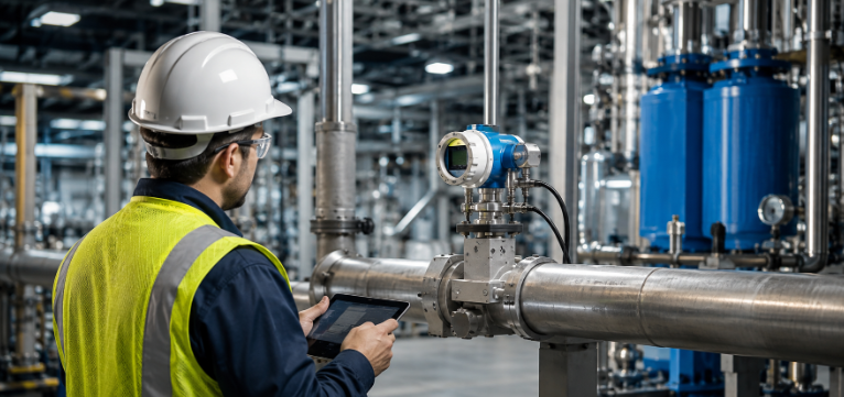
Compressed air is often referred to as the fourth utility in modern industrial plants. While electricity, water, and gas are strictly measured and managed, compressed air is frequently overlooked despite being one of the most expensive forms of energy to generate. Up to eighty percent of the electrical energy consumed by an air compressor is lost as heat, leaving only twenty percent as actual kinetic energy in the pneumatic stream. When compressed air networks operate without precise monitoring, unallocated costs, hidden leakages, and system pressure drops silently erode industrial profitability.
Achieving complete accountability across pneumatic networks requires advanced metering technology built for harsh industrial environments. Establishing an accurate baseline for air consumption allows facility managers to assign exact utility costs to individual production lines, detect systemic leakages before they escalate, and optimize compressor load sequences. Modern thermal mass flow measurement devices eliminate the need for manual estimations, turning vague utility bills into actionable operational insights.
Industrial facilities in Pakistan facing rising electricity tariffs and demanding sustainability targets rely on proven engineering partners for advanced flow measurement and metering solutions. Through expert technical consultation and local support provided by, engineering teams can easily integrate high precision measuring instruments into existing supply lines. By implementing the VA 570 energy monitoring flow meter, plant managers gain direct visibility into real time consumption, ensuring every cubic meter of air is accounted for and optimized for peak efficiency.
The True Cost of Unmonitored Compressed Air Systems
Unmonitored pneumatic systems are a primary source of hidden financial losses in heavy manufacturing, textile mills, pharmaceutical processing, and food packaging facilities. Generating compressed air requires continuous high voltage power, making compressors the single largest electrical load in many industrial facilities. When a plant operates without dedicated flow metering, managers cannot determine whether high electricity bills stem from legitimate production demands or severe systemic inefficiencies.
A major contributor to wasted energy is background leakage. In an unmonitored factory, small leaks at hose connections, worn seals, condensate traps, and pipe joints can account for twenty to thirty percent of total compressor output. These leaks force compressors to cycle frequently or run under partial load, accelerating mechanical wear and increasing maintenance requirements. Without continuous flow rate tracking, artificial demand keeps energy costs unnecessarily high.
In addition to leaks, misallocated utility expenses corrupt production economics. When compressed air is treated as a generic facility overhead rather than a direct cost of production, individual plant departments have no incentive to conserve air. High volume usage in one line gets blended into general facility costs, obscuring the true operational expenses of specific manufacturing processes. Precise metering transforms compressed air into a trackable resource, giving managers full financial transparency.
Fundamentals of Thermal Mass Flow Measurement
Understanding how thermal mass flow meters operate clarifies why they excel at compressed air accountability. Traditional volumetric meters, such as turbine or orifice plate meters, measure the volume of air flowing through a pipe at line conditions. Because compressed air changes density with variations in system pressure and ambient temperature, volumetric measurements require external pressure and temperature sensors to calculate standard volume flow.
Thermal mass flow sensors eliminate the need for separate compensation devices by operating on the principle of thermal dispersion. The sensor tip contains two stainless steel resistance temperature detectors. One sensor acts as a reference to measure the actual medium temperature, while the second sensor is heated to a constant temperature differential above the reference. As compressed air passes over the heated sensor, heat is transferred away from the probe tip into the moving gas stream.
The amount of heat removed is directly proportional to the mass flow rate of the compressed air, regardless of pressure fluctuations or temperature shifts. The internal electronics instantly convert this heat loss into standard volume units, such as cubic meters per hour or standard cubic feet per minute. This provides consistent, highly accurate measurements across wide operating ranges, capturing both subtle off peak leak rates and high velocity production loads.
Engineering Architecture of the CS Instruments Flow Meter
The design of this precision measurement instrument combines robust hardware with advanced diagnostic digital interfaces. Housed in a die cast aluminum enclosure rated up to IP 67 protection, the unit withstands extreme ambient temperatures, vibration, aggressive outdoor environments, and heavy industrial exposure. The sensor tip contains no moving parts, eliminating mechanical wear and drastically reducing long term maintenance requirements.
Every meter features an integrated measuring section constructed from high grade stainless steel, ensuring exact pipe alignment and consistent flow profiles. Unlike insertion probes that depend on precise manual positioning inside existing pipes, an integrated measuring section eliminates installation errors and ensures optimal flow conditions at the sensor probe. Standard flange and thread connections enable seamless retrofitting into air distribution lines.
The integrated illuminated display shows crucial real time operational parameters. Users can monitor current flow rates, cumulative total consumption, medium temperature, and peak demand values directly on the device. The meter supports a wide variety of communication protocols, including Modbus RTU, 4 to 20 mA analog outputs, pulse outputs, M Bus, Ethernet Modbus TCP, and Power over Ethernet, allowing smooth integration into plant wide SCADA or Energy Management Systems.
Key Technical Specifications and Operational Envelope
| Technical Parameter | Specification Range | Practical Advantage |
| Measuring Principle | Thermal Mass Flow Dispersion | No external pressure or temperature compensation required |
| Accuracy Standard | ±1.5% of measured value ±0.3% full scale | Delivers high precision for fiscal billing and audits |
| Optional Accuracy | ±1.0% of measured value ±0.3% full scale | Provides maximum accuracy for high-volume supply headers |
| Operating Pressure | Up to 16 bar standard (PN 40 optional) | Handles standard factory air networks and high-pressure lines |
| Media Temperature | Up to 180 °C (ATEX version up to 120 °C) | Suitable for hot discharge air directly downstream of compressors |
| Velocity Range | Up to 224 Standard Meters per Second | Accurately captures high peak velocities during full production |
| Pipe Diameters | DN 15 to DN 80 (Flanged or Threaded) | Matches common header sizes in industrial plants |
| Enclosure Rating | Robust Die-Cast Aluminum IP 67 | Resists harsh weather, moisture, and factory washdowns |
Strategic Installation and Sectional Accounting
Maximizing compressed air accountability requires a multi tiered metering strategy rather than relying on a single measurement point at the compressor room outlet. Placing flow meters at strategic points along the air distribution network establishes clear accounting boundaries and pinpoint visibility into consumption patterns.
The first level of metering should be placed on the main discharge headers directly after air treatment equipment, such as dryers and filtration units. This primary meter records total air generation, serving as the master benchmark for overall plant supply. Comparing total electrical energy input at the compressor control panel against total standard volume output from the flow meter yields the true system efficiency metric, expressed in kilowatt hours per standard cubic meter of air.
The second level involves installing inline meters at branch connections leading to specific production departments, halls, or buildings. Departmental metering enables accurate internal cost allocation, allowing finance and operations teams to charge utility expenses directly to specific production units. When department managers receive precise energy allocations based on actual consumption, they become active participants in air conservation efforts.
Continuous Leak Detection and Off Peak Auditing
While portable ultrasonic detectors help locate individual air leaks, continuous flow metering is necessary to evaluate total system leakage trends over time. Leakage rates are dynamic; as pipe connections flex, seals degrade, and fittings vibrate loose, air loss naturally increases over time unless continuously monitored.
The most effective method for quantifying plant wide leakage is the off peak baseline audit. During non production windows, such as weekend shifts or planned plant shutdowns, all pneumatic end use equipment is turned off while the compressed air system remains pressurized. Any flow recorded on the energy monitoring meter during these periods represents pure air loss through system leaks and artificial demand.
Because thermal mass meters maintain high accuracy even at very low flow velocities, they detect small leakage flows that traditional volumetric meters fail to register. By monitoring real time flow data during non-production hours, energy managers can set clear baseline targets for maintenance teams. When off-peak flow exceeds pre-established thresholds, maintenance personnel can be dispatched immediately to repair leaks before valuable energy is wasted.
Digital Integration with Industrial Energy Management Systems
In modern Industry 4.0 factories, isolated measurement devices are replaced by interconnected smart sensors that feed continuous real time data into centralized monitoring networks. Thermal mass meters easily interface with modern industrial automation infrastructure using flexible digital communication options.
Through Modbus RTU or Modbus TCP interfaces, flow meters transmit comprehensive data packages to Energy Management Systems, SCADA platforms, or programmable logic controllers. These data streams include instantaneous standard volume flow, mass flow, totalized volume, air temperature, and alarm states. Centralized software records this information continuously, creating long term trend lines, automated utility reports, and consumption forecasts.
Integrating compressed air flow data with electrical power meters allows energy management platforms to automatically compute real time system performance metrics. If compressor power draw remains constant while output flow steadily declines, the software alerts operators to potential compressor valve wear, clogged intake filters, or severe downstream leaks. Automated alarms notify maintenance personnel instantly when consumption spikes beyond normal production limits.
Comparison of Industrial Flow Metering Technologies
| Feature / Capability | Thermal Mass Meter | Vortex Flow Sensor | Differential Pressure |
| Primary Principle | Heat Transfer Rate | Vortex Shedding Frequency | Pressure Drop Across Orifice |
| Mass Flow Output | Direct Standard Measurement | Requires External Sensors | Requires External Sensors |
| Low Flow Sensitivity | Exceptional (Detects micro leaks) | Poor (Fails at low velocity) | Poor (Square root limitation) |
| System Pressure Loss | Minimal / Negligible | Moderate | Significant |
| Moving Parts | None | None | None |
| Calibration Maintenance | Low | Low | High (Impulse line maintenance) |
| Ideal Gas Application | Compressed Air, Nitrogen, Argon | High-Temp Steam, Mixed Gases | Stable High-Pressure Gas Headers |
Realizing ROI Through Air Network Accountability
Investing in high precision flow metering yields rapid financial returns by eliminating energy waste and optimizing maintenance schedules. In most manufacturing plants, compressed air energy costs exceed the initial purchase price of the compressor within its first year of operation. A dedicated flow monitoring system typically pays for itself within three to six months through identified leak reductions and improved operational efficiency.
Financial returns materialize across several key areas. First, eliminating background leaks reduces total compressor runtime, directly lowering monthly electricity costs. Second, optimizing air consumption reduces peak system demand, allowing facilities to avoid costly compressor capacity expansions when adding new production lines. Existing compressor setups can easily support expanded manufacturing capacity simply by eliminating wasted air.
Third, reliable flow measurement improves process stability. Excessive pressure drops across unmonitored networks often lead plant operators to increase compressor discharge pressure setpoints, which causes compressors to consume significantly more power. Maintaining proper network visibility allows facilities to stabilize air distribution pressures, improve product quality consistency, and extend the service life of pneumatic tools and equipment.
Frequently Asked Questions
Why is thermal mass measurement better for compressed air than volumetric measurement?
Thermal mass flow meters measure the mass of gas molecules passing the sensor directly, outputting standardized volume flow without needing external temperature or pressure compensation sensors. Volumetric meters only measure physical volume at line conditions, which changes constantly as system pressure and temperature fluctuate.
Can this flow meter be installed outdoors or in dusty environments?
Yes, the meter is built in a rugged die cast aluminum housing rated to IP 67 protection. This makes it completely dust tight and fully protected against heavy rain, washdowns, and harsh outdoor ambient conditions commonly found in industrial facilities.
How does continuous flow monitoring help in detecting pneumatic leaks?
By measuring total flow during non production periods or weekend shutdowns, any recorded air consumption represents background leakage. Continuous monitoring tracks these off peak flow rates over time, alerting maintenance teams as soon as leakage levels rise above acceptable baselines.
Does installing an inline flow meter cause significant pressure drops in air lines?
No, thermal mass flow meters feature an inline probe design with an extremely low obstruction profile inside the measuring section. This design keeps pressure loss virtually negligible, ensuring system pressure remains stable throughout the downstream distribution network.
What output signals are available to connect the meter to our factory SCADA system?
The meter comes standard with a 4 to 20 mA analog output, a pulse output, and a Modbus RTU interface. Optional digital interfaces include Ethernet Modbus TCP, M Bus, Power over Ethernet, and dual isolated analog channels, providing complete flexibility for system integration.
Final Thoughts
Achieving complete compressed air accountability is essential for modern industrial plants looking to control energy costs, reduce carbon emissions, and optimize pneumatic performance. By measuring standard mass flow directly, eliminating system pressure losses, and capturing subtle leakage flows, advanced thermal mass meters provide the accurate data needed for effective energy management. Implementing precision flow instrumentation transforms unmonitored air networks into fully trackable, highly efficient industrial utilities.
Engineering teams seeking expert technical selection, system integration, and authorized support can partner with to deploy tailored metering solutions across their facilities. Continuous flow monitoring turns hidden utility waste into measurable, long term operational savings.

 Arabic
 French
 Spanish
 Portuguese
 Deutsch
 Turkish
 Dutch
Dutch
 Italiano
 Russian
 Romaian
 Portuguese (Brazil)
 Greek
Greek
 Bengali